top of page
Repair and Modification of a classic Pulsar Modulator
This gallery documents the repair and modification of a Pulsar Modulator that I was given. I would have loved one of these back in the Seventies but it was outside my price range.
Apologies to Paul Mardon (who designed this classic) for "tweaking" it slightly but I have never owned any item of Disco Equipment that hasn't been personalised to my own needs. My original roadshow was completely hand build by me in 1978.
As with a lot of my projects, the enthusiasm to get started means I often forget to take the "before" picture. I found the picture below on the Internet and it looks pretty much like mine did except that mine wasn't in a wooden sleeve.
 I was given a Pulsar Modulator like this one. All the knobs were missing and the corner of the front panel was bent. Also something heavy had been dropped on it and two of the sliders were broken. | 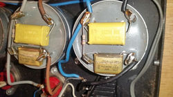 Opening it up for the first time revealed cracks in the Class X suppression capacitors so these were replaced. |
|---|---|
 A previous owner had added red wire jumpers on the rear of the Bulgin sockets to feed Channels 1 & 3 out on two additional pins. |  You can see the red jumper links on the other Bulgin socket as well. I removed these from both sockets. You can see a new fuseholder with no wires connected. This is the start of my modification to add a switched live output for driving UV Tubes built into my light boxes. |
 The mains cable had been cut off and was only about 300mm in length. I removed the cable restraint grommet, enlarged the hole slightly and brought it into the 21st Century by fitting a Powercon connector |  This is the relay I added in order to provide a switched live output for the UV tubes using Pin 6 of the Bulgin sockets |
 The new fuseholder has been wired to the relay with red wire and the relay wired to Pin 6 of the Bulgin sockets using yellow wire. |  The new fuseholder can be seen above the left hand Bulgin socket and the Powercon input is located where the original mains cable entry was. |
 The side and top panels were showing their age and had suffered a lot of wear and tear so a bit of a paint job was called for. |
bottom of page